Model Sailboat Plans on line
Most browsers will allow you to right click and open the jpg images. You can then save them to your machine.
This set of plans are based on drawing from John Fisher 2006. John may have new and updated drawings available. Check with http://groups.yahoo.com/search?query=star45 membership required.
I want to thank J. Herrmann, www.graphicLanguageOnline.com, for his assistance in converting pdf's to jpg drawing, adding color to the templates and adding the grid to the final images
You can print these drawing to many different sizes.They are not necessarily to scale.
20110503
S45 Class Sailboat Plans {line drawings} on-line


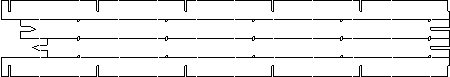
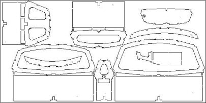
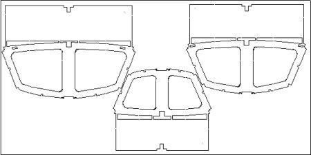
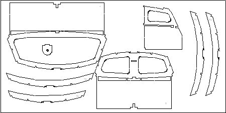
Star45 Hull Templates and shadows


The grid shown is set to 1/4 inch squares. So if you print the templates you can check the size by making sure the grid yields a 1/4 square.
Modelers will use different building materials for the model.These are JPG drawing and print outs may require adjustments to get the widths to correct sizing. For a Star45 AMYA class you need to make adjustments to allow for planking thickness. The rules establish the maximum allowable beam dimension and hull length.
Most browsers will allow you to right click and open the jpg files. You can then save them to your machine.
This set of templates are based on drawing from John Fisher back around August 2006. John may have new and updated drawings available. Check with http://groups.yahoo.com/search?query=star45 membership required.
If you want to scale to use for different model you can change the print out to give you a different grid size.
I want to thank J. Herrmann, www.graphicLanguageOnline.com, for his assistance in converting pdf's to jpg drawing, adding color to the templates and adding the grid to the final images.Rudder templates for a Star45 Class sailing model.The grid shown is set for 1/4 inch squares. So if you print the templates you can check the size by making sure the grid yields a 1/4 inch square.
This set of templates are based on drawing from John Fisher. John may have new and updated drawings available. Check with http://groups.yahoo.com/search?query=star45 membership required.
I want to thank J. Herrmann, www.graphicLanguageOnline.com, for his assistance in converting pdf's to jpg drawing, adding color to the templates and adding the grid to the final images.

These are half shadow that ar eplaced between the templates to add strength to the hull.
Star45 sailing model plans


Most browsers will allow you to right click and open the jpg images. You can then save them to your machine.
This set of plans are based on drawing from John Fisher 2006. John may have new and updated drawings available. Check with http://groups.yahoo.com/search?query=star45 membership required.
I want to thank J. Herrmann, www.graphicLanguageOnline.com, for his assistance in converting pdf's to jpg drawing, adding color to the templates and adding the grid to the final images
You can print these drawing to many different sizes.They are not necessarily to scale.
S45 Frames (aka bulkheads, shadows) on Mainzone.com
Every man, woman and child should enjoy the pleasure of building a wooden boat
The MainZone web page contains links to downloadable files for use in building the Star 45
This model is is built using frames otherwise known as shadows or bulkheads. The files for these frames reside on www.mainzone.com.
S45 Construction templates for laminating rudder


Rudder templates for a Star45 Class sailing model.The grid shown is set for 1/4 inch squares. So if you print the templates you can check the size by making sure the grid yields a 1/4 inch square.
This set of templates are based on drawing from John Fisher. John may have new and updated drawings available. Check with http://groups.yahoo.com/search?query=star45 membership required.
I want to thank J. Herrmann, www.graphicLanguageOnline.com, for his assistance in converting pdf's to jpg drawing, adding color to the templates and adding the grid to the final images.
Star 45 Construction templates Keel fin
.jpg)
.jpg)
.jpg)
.jpg)
Building templates for S45 Keel fin.
Originals drawings are based on 1/16 ply.
Modeler may want to use different building materials for the fin.
Final keel fin will be shaped the builder. Also these are JPG drawing and print outs may require adjustments to get the templates to correct sizing.
The grid shown is set for 1/4 inch squares. So if you print the templates you can check the size by making sure the grid is a 1/4 square. If you want to scale the keel fins for another model you can change the print out to give you a different grid size.
This set of templates are based on bolt mounting. The grid makes it easy to add to the template to have the keel extend into the hull or extend into the keel bulb. Modeler's choice.
Most browsers will allow you to right click and open the jpg images. You can then save them to your machine.
This set of templates are based on drawing from John Fisher 2006. John may have new and updated drawings available. Check with http://groups.yahoo.com/search?query=star45 membership required.
I want to thank J. Herrmann, www.graphicLanguageOnline.com, for his assistance in converting pdf's to jpg drawing, adding color to the templates and adding the grid to the final images.
RE: slots in (laser cut) frames and stringer from old forum notes 8.31.2010
Ray wrote: >
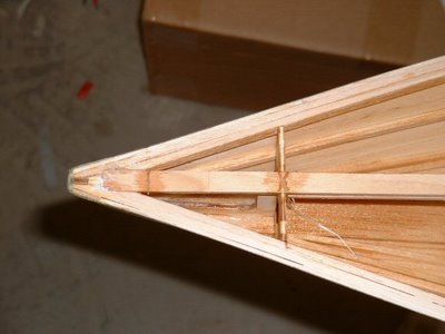
need to know what are the vertical > slot in frames 4,5,and 6 for also what size stringer goes into frames right > at the bottom where the bottom of hull meets the side of the boat also there > seems too be a slot for another brace on frames 4,5,and 6 directly under the > vertical slots.
Thanks Ray from Down Under
the vertical slots are for the radio tray if you use it. the extra vertical slots by the king plank are just extra strength for the keel area. Chines are 1/4" X 1/4" or 6.4mm sq.
John On 8/30/10,
The Star45 Model Sail Boat, A radio controlled, R/C, Sailing Model
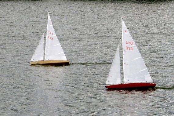
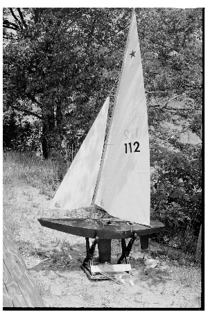
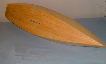
The Star 45 is a 45" long hard chine hull; semi-scale model of the full-size Olympic Star. They weigh 12 pounds plus, have 12 inch beam. They are easy to scratch build and sail. Well suited for building by by the novice builder and by the skipper looking for a classic looking model to race.
Hull stringers (aka rails)
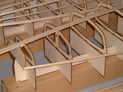
Photograph by John Fisher
Start at the transom with the rails and stringers. Start one side and go forward to station 9 or 10, then do the same on the other side. Then go all the way to the front with one side. Starting both sides at the same time keep the transom from twisting.
Photograph by John Whiteford
Steps toward building a sailing model
Building Displaying Sailing
Model Boats and Ships
So you want to build a sailing model
Find plans for a sailing model, buy or find on-line.
Join a model boat forum for advice.
Buy or borrow books on boat building.
Decide on type of planking and wood to be used to build the model.
Set aside a work space for building.
Review the bill of materials need to build the model and buy the materials.
Order deck and mast fittings.
Order mast (if you are buying the mast) and order sails (or sail material).
Choose the radio system, buy a sail control unit, Order keel bulb or get advice and discuss issues of building your own.
While the hull is under construction build:
Keel fin and ballast bulb
Rudder assembly
Make or assemble spars ( mast and booms)
Build cradle to hold boat under construction and when finished.
Test Radio System and sail control unit
After hull is planked:
Install keel trunk or make provisions for mounting keel.
Install radio and sail control unit, Then remove while construction continues.
Construct deck and hatches
Install/mount deck fittings
Test access to radio and sail control inside the hull.
Provide a exit guide for radio antenna so it can be attached to mast or stays.
Install power switch for turning off batteries
Test mount keel
Paint hull, rudder and keel
Assemble hull, rudder and keel
Set up mast and boom.
Install radio controls.
Check running rigging.
Attach Sails
dry sail model
--
Sail
Display
Storage
Star 45 Rudder Construction, using laser cut laminations


Star45 : Message: Re: [Star45] naca0009 rudder: "Re: [Star45] Photo's of naca0009 rudder
I am happy with how they turned out. I sent the production files to Stevens Monday, so you should be able to order a rudder if you need one. He doesn't have it posted yet, but if you call him he can cut them for you.
I built mine by clamping all the pcs together with the alignment pins in place (1/8 sq stock left over from stringers). Then CA'd it together with thin CA. I used my random orbital sander with 150 grit to shape it. Took about 15 min or so. With the different layers you can see if you are removing material evenly. Once sanded I sprayed the rudder with 3M 77, covered with 3 oz glass, one PC folding it over the leading edge so there is no seam on the leading edge. I then added resin and vac bagged in my handy food saver. The next day I pulled off the breather and peel ply, sanded smooth and varnished.
The glass is probably not needed since the core is made out of ply. I used the glass to ensure it is not coming apart and only adds another 10 min or so to do. With the vac bagging it is very smooth and uniform with only a little sanding required to remove the texture of the peel ply. I did buy a yard of breather and peel ply, but waxed paper with holes in it and paper towels can be substituted."
Drawings are available from the Yahoo Star45 group "files"
==


Sailing Model, AMYA Star45 Class | keel mount - using keel trunk
Here is how John Fisher built two Star45 keel trunks. First he make a aluminum mandrel that is the same size and shape of the top of his keels. Next he waxed the aluminum and then put a single layer of wax paper over the mandrel.
He used a light spray of 3M 77 to stick the ends together on the second one. The first one had a pc of tape, which is now a part of the trunk.
The mandrel with waxed paper is wrapped with glass which he again used 3M 77 to hold in place. He has not verified that this doesnt have any long term effects to the glass so use at your own risk. John used 2 layers 3.2 oz glass with glass tape on the top and bottom edges to help add some stregth. Usually he would add kevlar, but that is not allowed in the star's. One the glass was in place John wet the whole thing with resin. If you dont have any way to vac bag the trunk, just let it cure and remove the mandrel. The trunk weighted in at 1 oz.
John has a food vacuum sealer so he put a release paper over the top (wax paper with holes in it), then breather cloth (he hasused paper towels in the past), and then into a food saver bag for the night.
To remove the mandrel he used a hammer and a vice. He knows that sounds severe, but that is what it took to get the mandrel back out. He started by placing the mandrel into a vice with smooth jaws. The jaws were just far enough apart that the aluminum would fit between them, but not the fiber glass wrap. Then he tapped the mandrel out. He points out how much force it took for him to get this apart so you can design your keel top with this in mind.
Photo 01- mandrel before prep
Photo 03 -mandrel with glass, ready for resin
Photo 04-keel trunk in food saver bag. You can see the resin going into the breather cloth.
Photo 05 - keel trunk off the mandrel, note the tape. 2nd trunk used3M 77 instead.
Photo 06 - Trunk on the keel.

The following picture shows the way that John aligned the keel on his second boat.
Since the keel is plate and 1/8" thick I laid a straight edge on it and
aligned it with the pc at the center of the transom. I did this on both
sides to make sure it is centered as well.
To capture the top of the keel box he added 2 1/8" X 3/8" spruce blocks
to the top of the keel trunk and glued them to the king plank. The photo also shows the glass tape He used to reinforce the
radio tray.

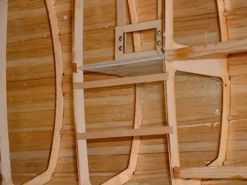
John Fisher photographer
===
here is an alternative keel trunk (from Uncle Dave)
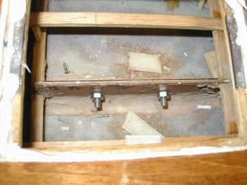
I poked my camera down into the Sirius 45 and snapped a couple of pictures showing how the keel is attached to allow it to be removed and another installed.
The keel is a aluminum fin with my flat bottomed bulb. The keel trunk is assembled over the keel fin before mounting the trunk in the hull. The trunk is pretty simple. Two pieces of 1/8 ply on either side of the fin. Cut flush across the top of the fin. Height is determined by the amount of the fin to extend into the hull. Length is determined by the shadows or braces to support the fin. A filler pieced goes between the sides so that fin can be slid own and out of the trunk.
Before gluing the trunk up it is very important to coat the insides of the trunk to make the sides of the trunk as water resistant as you can. The the fun part is placing two mounting bolts through the sides of the trunk and thought the keel fin. I think the two bolts in the picture were 1/2 long 3/8 inch dia.
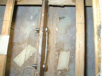
I placed a heavy wire through the both the bolt heads so I could turn the nuts on the other side.

With the nuts removed the two bolts simply push to one side and the keel fin mounted or removed as the case may be. In my models the height of the fin inside the model is low enough for a swing arm sail control to fit properly. I use Probar (now Dumas) SCU's.
Before building the deck I simply dropped the trunk (with keel fin) through the slot in the bottom of the hull so the trunk rests on the keelson. The hull being fiberglass the trunk if filleted with the bottom using some auto body resin-paste. I think I also used the resin paste to mount the keel trunk in my wooden models (memory escapes me its been years). The ends of the trunk are braced to the chine to with stand leverage forces from the heavy keel bulb and sailing stresses.
When the two bolts are tightened they not only hold the keel in place they also pull the sides of the of the trunk tightly together. With the tight fit one should expect the keel fin may stick in the trunk if some sort of lubricant (silicone) isn't used.
Weighing a keel-bulb while attached to a boat
The Star 45 R/C Model Sail Boat - Builders Journal: Weighing a keel while attached to a boat
Weighing a keel while attached to a boat
From "Larry Ludwig"
"Weighing a keel while attached to a boat can be done with a high degree of accuracy. You can test this out on a boat with a removeable keel. Lay the boat on it's side with the keelbulb on the scale with the keel parallel to the table. Then take the keel off and weight it and you will be amazed that they are nearly the same, as in within 95% or better."
Sails for AMYA Star 45 Sailing Model
AMYA Star 45 Class Rules, 2006, Sails
2.1 Sails may be of single or multi-paneled construction. Sail material shall be unrestricted.
2.2 All sails are to be cut to comply with the following maximum dimensions when measured by the procedure as outlined in the "AMYA Regulations". Dimensions shown are measured 'Edge of Cloth" to "Edge of Cloth" and are in inches.
2.3
MAIN JIB
Luff 62.75 42.50
Foot 25.50 15.75
Leech 65.50 37.00
Roach 2.00 0.50
Head 0.75 0.75
Foot Round 0.50 0.50
2.4 All sails, main and jib, will be cut with either a straight head to clew leech with no roach, or a fair
curved head to clew leech with the maximum roach point occurring approximately one half the distance from the clew to head. Divide a straight line from the aft corners of the Clew and Head into four (4) equal sections. Then, for the Main Sail, maximum offset from edge of cloth for the Roach at the quarter points to be 1.75" and the offset at the mid-point to be 2.0". For the Jib, the offset at the quarter points to be 0.375" and at the mid-point to be 0.50". Sails cut with a straight leech at the maximum roach allowance are prohibited from use on the Star 45 Class Yacht.
2.5 The mainsail gooseneck or attachment will be attached to the Mast between 0.50 inch minimum to 4.0 inch maximum measured from the deck.
2.6 Battens are allowed on the mainsail but are restricted to 4 in number, equally spaced along the leech and may not exceed 8.50 inches in length. Battens are not permitted in the jib sail.
2.7 Sailmakers must conform to the above measurements.
9.1 Each yacht shall carry on her main sail the class 5 point "STAR EMBLEM" and an assigned AMYA registration number. The star shall be at least 2 inches in size (measured from point to point across the flat of the star) and positioned above the registration number. Registration numbers shall be at least 3 inches in height and at least 3/8 inch thick. Both star and registration numbers will be placed on the upper half of the mainsail on both port and starboard sides of the mainsail and shall be positioned so as to be easily read from either side.
Sailing Model, AMYA Star45 Class | "stringers"
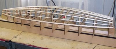
adding the rails. Notice that the rails are made of two pcs. 1/4X1/8 for the first one and then 3/8X1/8 for the second. You need to start both at the transom. Start at the transom with the rails and stringers. Start one side and go forward to station 9 or 10, then do the same on the other side. Then go all the way to the front with one side. Starting both sides at the same time keep the transom from twisting.
Photographs by John Fisher

adding the bottom stringers. 1/8X1/8.
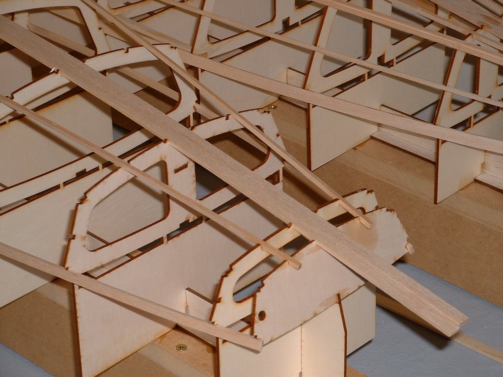
Photo shows the close stringer sanded to fit the side and the back stringer still need to be sanded. John used a sanding block and sand the sides to match the bottom curve. Balsa sands really easy so this is pretty quick. He used 220 grit paper.

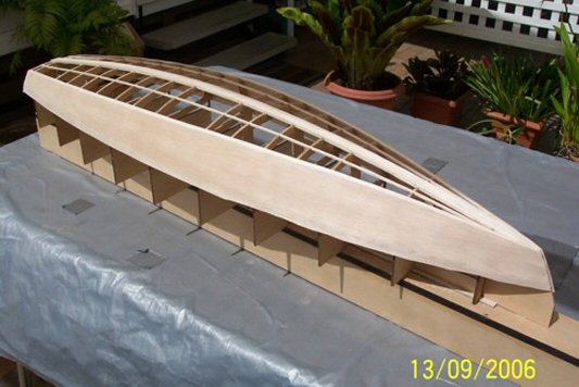
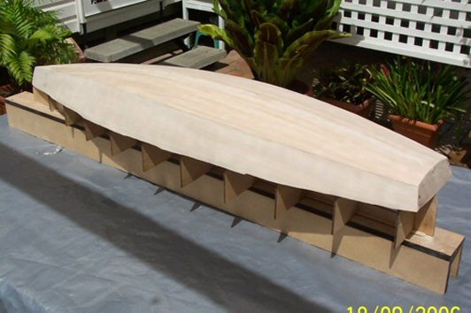
Star 45 Construction by : John Whiteford, Rochedale, Queensland, Australia
Following are three Photographs by John Whiteford

Subscribe to:
Posts (Atom)