The mainsail and jib on the Star 45 are self tending. That is they can swing from side to side as the model tacks without requiring the sheets to be tended.
Originally on the old model the jib was loose footed and did not use a jib boom (aka a jib club). The addition of a jib club allowed the jib shape to be controlled.
Like the main sail the foot of the jib will fly up is some type of vang is not in place. Typically a swivel is placed along the forward end of the jib boom and clipped to a deck fitting (aka jib rack).
Look at the jib as a triangle. The halyard pulling the head of the jib places a force on the jib swivel. As the swivel is moved forward and aft along the jib boom the leach of the sail has more or less ability to rise. The head of the jib also moves off center.
It is possible to find jib boom fittings that anchor the forward end of the jib to the bow and use a vang to control the lift of the boom. These are known as radial jib fittings. The jib stay attaches to the radial fitting. This has the advantage of staying taught against the back stay as the sails are trimmed,
The jib boom and swivel also pull against the back stay. Since the jib stay attached to the jib boom in this arrangement moves off center and is subject to varying wind forces the tension on the jib stay and back stay will vary.
The driving force of the sails is changed when the slot between the mast and jib changes. Finding the best spot for the mast and jib swivel/radial fitting adds the challange of setting up the sails prior to sailing.
Showing posts with label yacht. Show all posts
Showing posts with label yacht. Show all posts
20150825
20150813
Wood choices and AMYA rules for Star45 Class
Hulls may be planked using any number of types of wood, including thin aircraft plywood, cedar, balsa, etc.
The Star 45 is a terrific boat for sport sailing and family fun. If you want to race other Star 45's you should build to the AMYA Class rules.
Here are key 2006 AMYA Star 45 Class Rules,section 1.0 Hull:
1.1 The Star 45 Class establishes as their approved plans a set of lines and drawings as the approved reference and construction plans for the class. These plans are scaled and appropriately modified for the use of modelers building a 45-inch model of the Star Boat. Existing plans supplied by kit manufacturers, etc. are grandfathered. New molds, plugs and scratch built models shall conform to the approved plans and specifications.
1.2 Hull length will be 45 inches (plus or minus one half (1/2) inch overall. (NOTE: this does not include any chain plate for backstay attachment, or 1/4 inch bow bumper if used. However, if the chain plate is attached to the transom or overhangs the transom, it may not extend beyond the transom more than 3/8 of a inch.) Hulls may not be less than 11 inches nor exceed 12 inches in beam when measured at the widest point on the deck. (Rubrails are not included in measuring but will not exceed 1/4 inch of thickness/width.)
1.3 In the event of a builder choosing to scratch or hand build a Star 45 Yacht, the builder must adhere to the class approved reference and construction drawings, as obtained from the AMYA Ships Store, as in the builders ability. A second consideration in scratch building is to ensure that safe and sound building practice be maintained.
1.4 All hulls will be constructed of wood or fiberglass or a combination of wood and fiberglass and be a minimum of 16 ounces when weighed before attachment of the deck and keel. This weight must be verified by another member of the Star 45 Class using the Class Measurement Form.
1.5 Decks shall be constructed of wood, fiberglass or plastic laminate material.
1.6 All hulls shall be the standard hard-chine hull. Hulls may be built with a sheer at scale height or with a sheer no more than one inch higher than scale (when measured at the point of maximum depth of sheer.)
1.7 All fiberglass and wood hulls will have a name plate permanently attached to the inside of the hull so as to be seen when the hatch cover is removed.
1.8 At or before its first Sanctioned Regatta the newly built model yacht must be measured using, as reference, the approved measurement form and signed by not less than the owner of the model yacht and one other member of the class. This measurement form shall become, with the registration card, a permanent record of this model yacht.
1.9 The AMYA Star 45 Class recognizes and approves the molds and manufacturer and/or kit packagers of Star 45 molded hulls and kits in existence at the time of approval of these specifications. These sources will be approved sources for the class. New manufacturers will be directed to submit the first of their product to the Class Secretary for approval.
1.10 No maximum weight is specified, however, no yacht will weigh less than 12 pounds when fully rigged ready to sail. This means with all gear, rigging, sails, radio components, batteries and ballast placed and secured on board.
1.11 Bow Bumpers are mandatory for all class registered STAR 45 yachts. Bow bumpers are limited to three eight's of an inch (3/8") overhang. Bow bumpers shall be excluded in the overall length measurement, whether recessed in or otherwise attached to the bow stem. Bow bumpers must be of resilient fabrication to minimize damage to another yacht in the event of a collision.
The Star 45 is a terrific boat for sport sailing and family fun. If you want to race other Star 45's you should build to the AMYA Class rules.
Here are key 2006 AMYA Star 45 Class Rules,section 1.0 Hull:
1.1 The Star 45 Class establishes as their approved plans a set of lines and drawings as the approved reference and construction plans for the class. These plans are scaled and appropriately modified for the use of modelers building a 45-inch model of the Star Boat. Existing plans supplied by kit manufacturers, etc. are grandfathered. New molds, plugs and scratch built models shall conform to the approved plans and specifications.
1.2 Hull length will be 45 inches (plus or minus one half (1/2) inch overall. (NOTE: this does not include any chain plate for backstay attachment, or 1/4 inch bow bumper if used. However, if the chain plate is attached to the transom or overhangs the transom, it may not extend beyond the transom more than 3/8 of a inch.) Hulls may not be less than 11 inches nor exceed 12 inches in beam when measured at the widest point on the deck. (Rubrails are not included in measuring but will not exceed 1/4 inch of thickness/width.)
1.3 In the event of a builder choosing to scratch or hand build a Star 45 Yacht, the builder must adhere to the class approved reference and construction drawings, as obtained from the AMYA Ships Store, as in the builders ability. A second consideration in scratch building is to ensure that safe and sound building practice be maintained.
1.4 All hulls will be constructed of wood or fiberglass or a combination of wood and fiberglass and be a minimum of 16 ounces when weighed before attachment of the deck and keel. This weight must be verified by another member of the Star 45 Class using the Class Measurement Form.
1.5 Decks shall be constructed of wood, fiberglass or plastic laminate material.
1.6 All hulls shall be the standard hard-chine hull. Hulls may be built with a sheer at scale height or with a sheer no more than one inch higher than scale (when measured at the point of maximum depth of sheer.)
1.7 All fiberglass and wood hulls will have a name plate permanently attached to the inside of the hull so as to be seen when the hatch cover is removed.
1.8 At or before its first Sanctioned Regatta the newly built model yacht must be measured using, as reference, the approved measurement form and signed by not less than the owner of the model yacht and one other member of the class. This measurement form shall become, with the registration card, a permanent record of this model yacht.
1.9 The AMYA Star 45 Class recognizes and approves the molds and manufacturer and/or kit packagers of Star 45 molded hulls and kits in existence at the time of approval of these specifications. These sources will be approved sources for the class. New manufacturers will be directed to submit the first of their product to the Class Secretary for approval.
1.10 No maximum weight is specified, however, no yacht will weigh less than 12 pounds when fully rigged ready to sail. This means with all gear, rigging, sails, radio components, batteries and ballast placed and secured on board.
1.11 Bow Bumpers are mandatory for all class registered STAR 45 yachts. Bow bumpers are limited to three eight's of an inch (3/8") overhang. Bow bumpers shall be excluded in the overall length measurement, whether recessed in or otherwise attached to the bow stem. Bow bumpers must be of resilient fabrication to minimize damage to another yacht in the event of a collision.


20110503
The Star45 Model Sail Boat, A radio controlled, R/C, Sailing Model

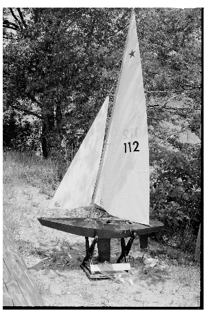
The Star 45 is a 45" long hard chine hull; semi-scale model of the full-size Olympic Star. They weigh 12 pounds plus, have 12 inch beam. They are easy to scratch build and sail. Well suited for building by by the novice builder and by the skipper looking for a classic looking model to race.
Sailing Model, AMYA Star45 Class | keel mount - using keel trunk
Here is how John Fisher built two Star45 keel trunks. First he make a aluminum mandrel that is the same size and shape of the top of his keels. Next he waxed the aluminum and then put a single layer of wax paper over the mandrel.
He used a light spray of 3M 77 to stick the ends together on the second one. The first one had a pc of tape, which is now a part of the trunk.
The mandrel with waxed paper is wrapped with glass which he again used 3M 77 to hold in place. He has not verified that this doesnt have any long term effects to the glass so use at your own risk. John used 2 layers 3.2 oz glass with glass tape on the top and bottom edges to help add some stregth. Usually he would add kevlar, but that is not allowed in the star's. One the glass was in place John wet the whole thing with resin. If you dont have any way to vac bag the trunk, just let it cure and remove the mandrel. The trunk weighted in at 1 oz.
John has a food vacuum sealer so he put a release paper over the top (wax paper with holes in it), then breather cloth (he hasused paper towels in the past), and then into a food saver bag for the night.
To remove the mandrel he used a hammer and a vice. He knows that sounds severe, but that is what it took to get the mandrel back out. He started by placing the mandrel into a vice with smooth jaws. The jaws were just far enough apart that the aluminum would fit between them, but not the fiber glass wrap. Then he tapped the mandrel out. He points out how much force it took for him to get this apart so you can design your keel top with this in mind.
Photo 01- mandrel before prep
Photo 03 -mandrel with glass, ready for resin
Photo 04-keel trunk in food saver bag. You can see the resin going into the breather cloth.
Photo 05 - keel trunk off the mandrel, note the tape. 2nd trunk used3M 77 instead.
Photo 06 - Trunk on the keel.

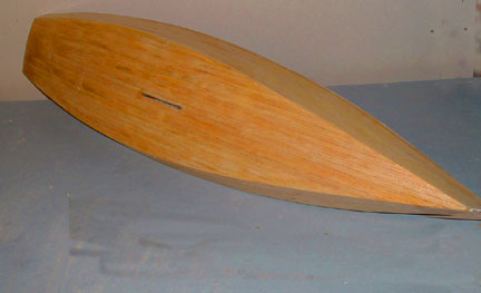
The following picture shows the way that John aligned the keel on his second boat.
Since the keel is plate and 1/8" thick I laid a straight edge on it and
aligned it with the pc at the center of the transom. I did this on both
sides to make sure it is centered as well.
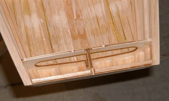
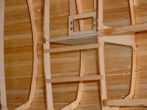
To capture the top of the keel box he added 2 1/8" X 3/8" spruce blocks
to the top of the keel trunk and glued them to the king plank. The photo also shows the glass tape He used to reinforce the
radio tray.

John Fisher photographer
===
here is an alternative keel trunk (from Uncle Dave)
I poked my camera down into the Sirius 45 and snapped a couple of pictures showing how the keel is attached to allow it to be removed and another installed.
The keel is a aluminum fin with my flat bottomed bulb. The keel trunk is assembled over the keel fin before mounting the trunk in the hull. The trunk is pretty simple. Two pieces of 1/8 ply on either side of the fin. Cut flush across the top of the fin. Height is determined by the amount of the fin to extend into the hull. Length is determined by the shadows or braces to support the fin. A filler pieced goes between the sides so that fin can be slid own and out of the trunk.
Before gluing the trunk up it is very important to coat the insides of the trunk to make the sides of the trunk as water resistant as you can. The the fun part is placing two mounting bolts through the sides of the trunk and thought the keel fin. I think the two bolts in the picture were 1/2 long 3/8 inch dia.
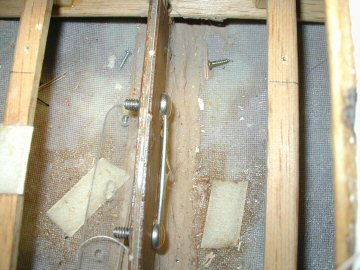
I placed a heavy wire through the both the bolt heads so I could turn the nuts on the other side.

With the nuts removed the two bolts simply push to one side and the keel fin mounted or removed as the case may be. In my models the height of the fin inside the model is low enough for a swing arm sail control to fit properly. I use Probar (now Dumas) SCU's.
Before building the deck I simply dropped the trunk (with keel fin) through the slot in the bottom of the hull so the trunk rests on the keelson. The hull being fiberglass the trunk if filleted with the bottom using some auto body resin-paste. I think I also used the resin paste to mount the keel trunk in my wooden models (memory escapes me its been years). The ends of the trunk are braced to the chine to with stand leverage forces from the heavy keel bulb and sailing stresses.
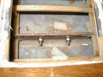
When the two bolts are tightened they not only hold the keel in place they also pull the sides of the of the trunk tightly together. With the tight fit one should expect the keel fin may stick in the trunk if some sort of lubricant (silicone) isn't used.
Sails for AMYA Star 45 Sailing Model
AMYA Star 45 Class Rules, 2006, Sails
2.1 Sails may be of single or multi-paneled construction. Sail material shall be unrestricted.
2.2 All sails are to be cut to comply with the following maximum dimensions when measured by the procedure as outlined in the "AMYA Regulations". Dimensions shown are measured 'Edge of Cloth" to "Edge of Cloth" and are in inches.
2.3
MAIN JIB
Luff 62.75 42.50
Foot 25.50 15.75
Leech 65.50 37.00
Roach 2.00 0.50
Head 0.75 0.75
Foot Round 0.50 0.50
2.4 All sails, main and jib, will be cut with either a straight head to clew leech with no roach, or a fair
curved head to clew leech with the maximum roach point occurring approximately one half the distance from the clew to head. Divide a straight line from the aft corners of the Clew and Head into four (4) equal sections. Then, for the Main Sail, maximum offset from edge of cloth for the Roach at the quarter points to be 1.75" and the offset at the mid-point to be 2.0". For the Jib, the offset at the quarter points to be 0.375" and at the mid-point to be 0.50". Sails cut with a straight leech at the maximum roach allowance are prohibited from use on the Star 45 Class Yacht.
2.5 The mainsail gooseneck or attachment will be attached to the Mast between 0.50 inch minimum to 4.0 inch maximum measured from the deck.
2.6 Battens are allowed on the mainsail but are restricted to 4 in number, equally spaced along the leech and may not exceed 8.50 inches in length. Battens are not permitted in the jib sail.
2.7 Sailmakers must conform to the above measurements.
9.1 Each yacht shall carry on her main sail the class 5 point "STAR EMBLEM" and an assigned AMYA registration number. The star shall be at least 2 inches in size (measured from point to point across the flat of the star) and positioned above the registration number. Registration numbers shall be at least 3 inches in height and at least 3/8 inch thick. Both star and registration numbers will be placed on the upper half of the mainsail on both port and starboard sides of the mainsail and shall be positioned so as to be easily read from either side.
Sailing Model, AMYA Star45 Class | "stringers"
adding the rails. Notice that the rails are made of two pcs. 1/4X1/8 for the first one and then 3/8X1/8 for the second. You need to start both at the transom. Start at the transom with the rails and stringers. Start one side and go forward to station 9 or 10, then do the same on the other side. Then go all the way to the front with one side. Starting both sides at the same time keep the transom from twisting.
Photographs by John Fisher

adding the bottom stringers. 1/8X1/8.
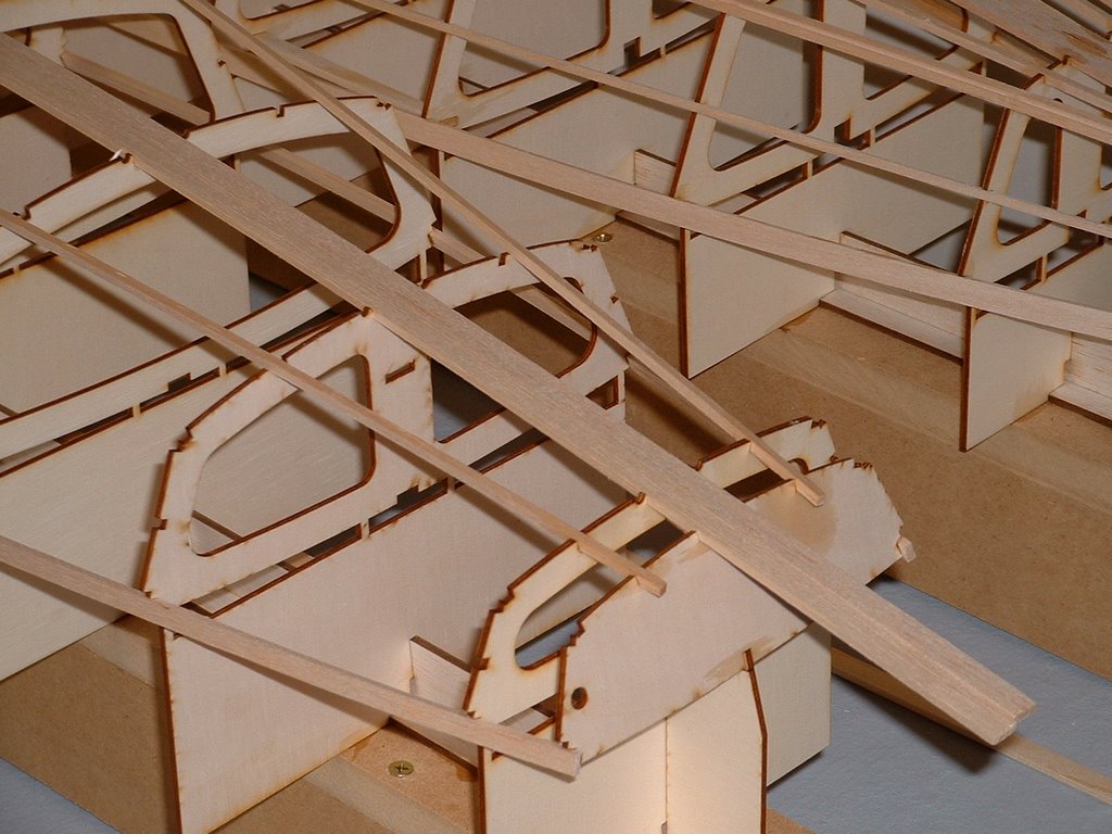
Photo shows the close stringer sanded to fit the side and the back stringer still need to be sanded. John used a sanding block and sand the sides to match the bottom curve. Balsa sands really easy so this is pretty quick. He used 220 grit paper.

Star 45 Construction by : John Whiteford, Rochedale, Queensland, Australia
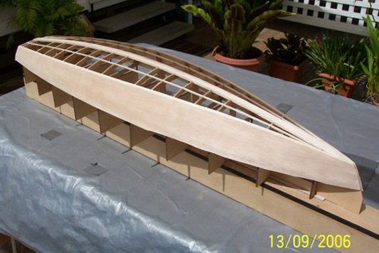
Following are three Photographs by John Whiteford

Sailing Model, AMYA Star45 Class | framing up
Builder's notes:
The vertical part of the jig is installed once the stern section is assembled. These parts keep the shadows sq and vertical.
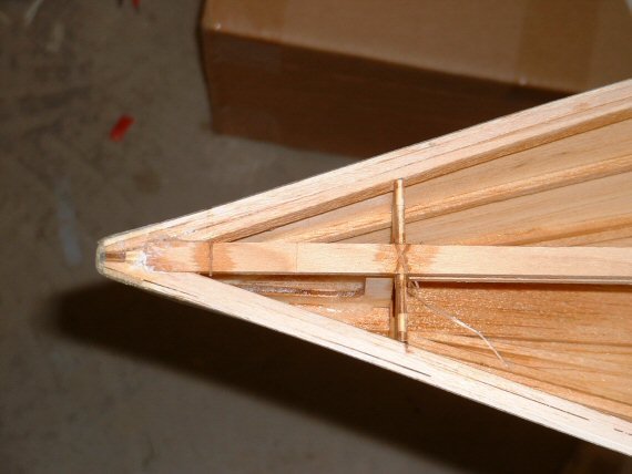
Adding of the stringers, rails and chine.
For the single chine version, there is only one pc of material for the chine instead of 2 as shown in the photo's.
Remember the 1/8X3/8 spruce for the chain plates. This needs to be installed before the rails go in.
The vertical part of the jig is installed once the stern section is assembled. These parts keep the shadows sq and vertical.
Adding of the stringers, rails and chine.
For the single chine version, there is only one pc of material for the chine instead of 2 as shown in the photo's.
Remember the 1/8X3/8 spruce for the chain plates. This needs to be installed before the rails go in.
Sailing Model, AMYA Star45 Class | Planking bottom of hull
From John Fisher:
 Photograph by John Fisher
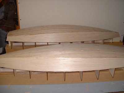
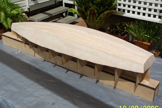
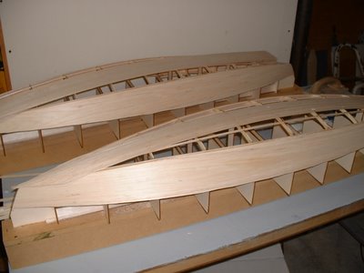
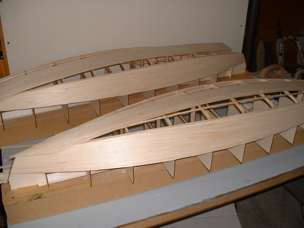
Since it was requested here are a couple of photo's of planking the
bottom of my two wood/glass stars. photo 01 is the bottom of the first
star about half way done. Planks are 1/16 X 3/8 balsa. These were cut
from a 48" long sheet. Weigh your balsa before buying it. I would not
use a 3 X 48 sheet that weighed in at more than 22g. It takes 3 sheets
to cover the bottom and you could add another 1 to 1.5 oz by using
heavy balsa.
I started in the middle and worked to the outside. I sprayed the
shadows with kicker, then put down a plank, then added super fast CA to
hold it down. If the kicker was not dry enough it would cure before it
wicked into the joint which would cause the next plank to not fit
correctly. I had some variation in the planks, but once they were
glassed the bottom smoothed out quite a bit.
If I were to do another one I would add the half frames. I will be
adding them to the DXF files in the next couple of days for anyone
wishing to cut a set.
Picture shows the bottom after it was completely planked. On the
second boat I got a nice pattern on the bottom since the balsa sheets
had different grain structure. I sanded the sided flush and got the
bottom relatively smooth, but not perfect. With the balsa planks they
were flexible and if sanded too much you get thin spots at the frames.
The glass smoothed out inperfections. If doing a hard wood bottom the
planks should fit better than what I did with the balsa.
John Fisher 2006 August 15
 Photograph by John Fisher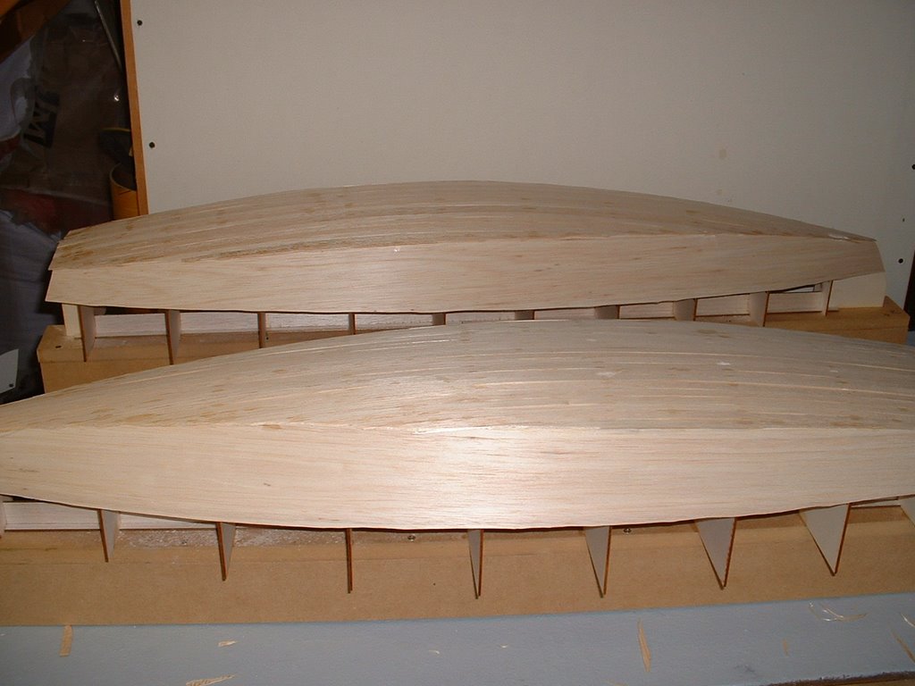
Photograph by John Fisher
Since it was requested here are a couple of photo's of planking the
bottom of my two wood/glass stars. photo 01 is the bottom of the first
star about half way done. Planks are 1/16 X 3/8 balsa. These were cut
from a 48" long sheet. Weigh your balsa before buying it. I would not
use a 3 X 48 sheet that weighed in at more than 22g. It takes 3 sheets
to cover the bottom and you could add another 1 to 1.5 oz by using
heavy balsa.
I started in the middle and worked to the outside. I sprayed the
shadows with kicker, then put down a plank, then added super fast CA to
hold it down. If the kicker was not dry enough it would cure before it
wicked into the joint which would cause the next plank to not fit
correctly. I had some variation in the planks, but once they were
glassed the bottom smoothed out quite a bit.
If I were to do another one I would add the half frames. I will be
adding them to the DXF files in the next couple of days for anyone
wishing to cut a set.
Picture shows the bottom after it was completely planked. On the
second boat I got a nice pattern on the bottom since the balsa sheets
had different grain structure. I sanded the sided flush and got the
bottom relatively smooth, but not perfect. With the balsa planks they
were flexible and if sanded too much you get thin spots at the frames.
The glass smoothed out inperfections. If doing a hard wood bottom the
planks should fit better than what I did with the balsa.
John Fisher 2006 August 15
Star 45 R/C model sail boat | Keels and keel-ballast bulbs
AMYA Star 45 Class Rules, 2006, KEELS AND BALLAST BULBS
7.1 Keel will be of the style known as drop, and will be of the FIN and BULB type.
7.2 Keel fins may be solid or hollow and constructed of reinforced plastic, plastic laminates, fiberglass, wood or metal. (Note: Strength and integrity of the keel fins must be maintained whether built solid or hollow.) Keel fin shape is not specified but must follow the general shapes outlined on the reference drawing. However, keels will not be less than 6 inches nor more than 8 inches long (Fore and Aft) at the keel/hull junction, nor less than 4 inches nor more than 6 inches long (Fore and Aft) at the keel/ballast bulb junction.
7.3 Keels, keel fins and ballast bulbs may be removable, however, they may not be changed, interchanged, substituted or otherwise manipulated once any heat or series of heats in which scores will be compiled, has started. Mechanically movable keels or ballast bulbs are specifically prohibited from use in Star 45 Class Yachts.
7.4 Ballast bulbs may be constructed of any material not prohibited by the AMYA. The actual shape is left to the builder's discretion, but will not exceed 9.75 (9 3/4) inches from the front of the keel bulb to the rearmost point of the keel or bulb.
7.5 Total drop (length) of the keel fin/ballast bulb combination will not exceed 11.5 (11 1/2) inches when measured from the keel/hull junction, before any fillers or streamlining is added.
7.6 Ballast may be made from any readily available material, such as poured lead, lead shot, etc. (Note: When using material such as lead shot, the mass must be solidified through the use of a bonding agent such as fiberglass or epoxy resin, plaster of paris, poured over and through in order to create a solid mass.)
7.7 Race directors may elect to use a template based on the construction plans to determine the keel length (depth).
7.8 Keel depth shall be measured from the center of the keel fin at the hull to the bottom of the ballast bulb. This measurement is from the edge of the bottom of the hull as it meets the side of the keel and should be determined during construction and before any fillet or fairing is added.
7.9 The Star 45 Class specifically excludes radio equipment, sail controls and batteries (power cells) from being considered ballast. This specification defines ballast as anything carried aboard the model for the main purpose of changing the weight distribution of the model and/or weight of the model. Ballast shall be fixed in place by gluing, fiberglassing, or bolting (bolts and screws).
7.9.1 Ballast may not be removed or relocated during any one regatta. The use of Velcro or similar quick release fasteners is prohibited as methods of mounting ballast.
Sailing Model, AMYA Star45 Class | planking sides
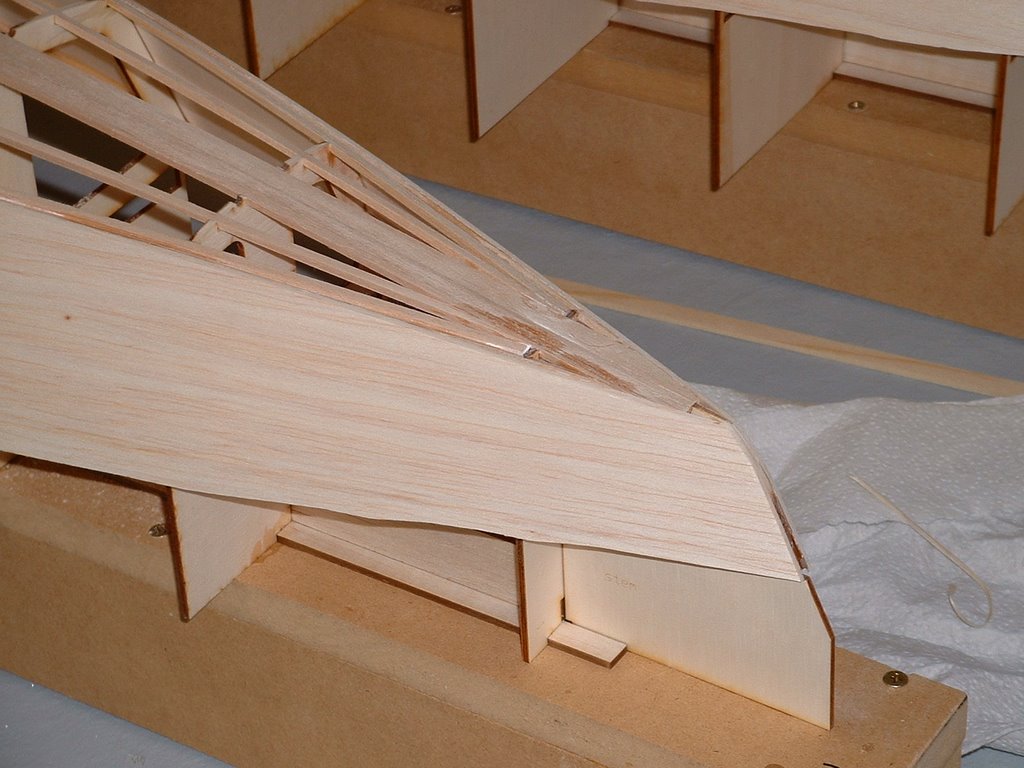
Photo showing adding the side planking and sanding to get ready for bottom planking.
He used 1/16" balsa for my hulls since he will be covering it with glass.
It probably will work the same if you are using harder woods, but you will probably want to trace the outline onto the wood and cut close to shape before gluing it on.
Photo showing side plank after being glued on. John used thin ca and glued the 4" wide plank on.
Make sure it is located correctly before starting gluing.
Photo showing the planks after being trimmed close to the stringers.
John used a # 11 Exacto to trim the balsa planks.
Go slow and take multiple passes here. You don't want to remove too much material or you will get a gap when the bottom is planked. Also trim the rails close at this point.
The rails/side joint will be finished once the hull is taken off the board.
Photo showing the close stringer sanded to fit the side and the back stringer still need to be sanded.
John used a sanding block and sand the sides to match the bottom curve. Balsa sands really easy so this is pretty quick. He used 220 grit paper
Photo showing both hulls with sides matching the bottom curve and ready for planking.
Photo showing the bow sections after sanding and ready for bottom planking.
==
http://groups.yahoo.com/group/Star45/ for discussions with other Star 45 sailors.
He used 1/16" balsa for my hulls since he will be covering it with glass.
It probably will work the same if you are using harder woods, but you will probably want to trace the outline onto the wood and cut close to shape before gluing it on.
Photo showing side plank after being glued on. John used thin ca and glued the 4" wide plank on.
Make sure it is located correctly before starting gluing.
Photo showing the planks after being trimmed close to the stringers.
John used a # 11 Exacto to trim the balsa planks.
Go slow and take multiple passes here. You don't want to remove too much material or you will get a gap when the bottom is planked. Also trim the rails close at this point.
The rails/side joint will be finished once the hull is taken off the board.
Photo showing the close stringer sanded to fit the side and the back stringer still need to be sanded.
John used a sanding block and sand the sides to match the bottom curve. Balsa sands really easy so this is pretty quick. He used 220 grit paper
Photo showing both hulls with sides matching the bottom curve and ready for planking.
Photo showing the bow sections after sanding and ready for bottom planking.
==
http://groups.yahoo.com/group/Star45/ for discussions with other Star 45 sailors.
Sailing Model, AMYA Star45 Class | building rudder
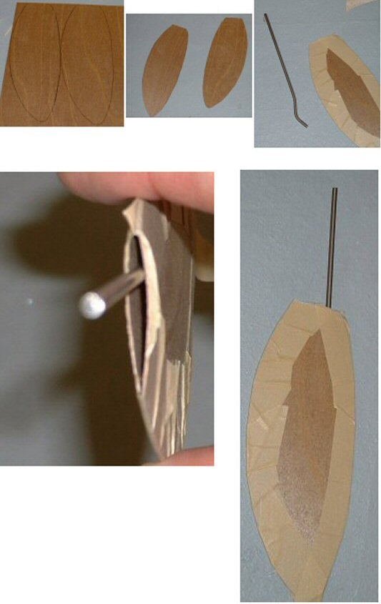
Here are some photo's showing one way to build a rudder quickly and easily. The quick overview is cut out the shape in a thin material, tape the sides together, insert the rudder shaft, fill the inside of the rudder with epoxy. This takes about 10 min or so to do. Followed by installation in your boat.
John Fisher
Lay out the rudder shape on a sheet of 1/64 ply. On other class boats John used a single layer of a 6 oz carbon fiber layup, so you could also lay up some fiberglass for use on the star. To do a glass layup, just take a sheet of 6 oz or heavier fiberglass, a sheet of lexan or plexiglass, and some resin. The first step is to spread resin on the plexiglass, then apply the fiberglass and then make sure it is all wetted out. Once cure flex the plexiglass and the layup will pop off.
Shows the two sides cut out of plywood, these could be fiberglass instead. Straight sided shapes like shown and the star plans are easier to make.
Tape the two sides together with masking tape. With curved shapes He taped them together then insert the shaft and resin. If you use straight sides on the rudder you can tape one side and then open it up like a book, apply resin, then close and tape shut. The open book method uses less resin but only works with sq or straight sided shapes.
Note the bend John put in the shaft to prevent it from turning inside the rudder.
Shows the top open to pour in resin. John uses a syringe to pour in resin once the shaft is in place. You can add micro balloons to the resin if concerned about weight.
Installing Rudder in Star 45


John Fisher photographer
downloadable files for cutting laser shadows (aka, frames, bulkheads)
Here is another set of downloadable files for Star 45 shadows (aka templates, bulkheads). They reside on my site: http://www.mainzone.com/star45frames/.
You can use your browser, go to www.mainzone.com/star45frames/ select the files you want and they will download to your machine. BTW, only the single stringer files are available from Mainzone.com/.
--
John Fisher provided the CAD files for laser cutting frames. These frames are trimmed based on 1/16 thick planking.
Contact John Fisher to obtain custom DXF and PDF files and to report any issues with the files. email John racer577 at citystar.com (remove the space between 7 and at, change at to @, and remove the space between at and citystar)
--
Most laser plotters used to cut materials require either DXF files or DWG files
DXF files are CAD vector data - plotter files that instruct a device to "start here" then put the (pen, knife) down and "move to, go to"...
Select dxf or dwg based the file type used by your laser cutter.
A CAD viewer or CAD application is required to view the contents. When you download some file types you may see "words" not pictures since these are files with machine commands.
You can use your browser, go to www.mainzone.com/star45frames/ select the files you want and they will download to your machine. BTW, only the single stringer files are available from Mainzone.com/.
--
John Fisher provided the CAD files for laser cutting frames. These frames are trimmed based on 1/16 thick planking.
Contact John Fisher to obtain custom DXF and PDF files and to report any issues with the files. email John racer577 at citystar.com (remove the space between 7 and at, change at to @, and remove the space between at and citystar)
--
Most laser plotters used to cut materials require either DXF files or DWG files
DXF files are CAD vector data - plotter files that instruct a device to "start here" then put the (pen, knife) down and "move to, go to"...
Select dxf or dwg based the file type used by your laser cutter.
A CAD viewer or CAD application is required to view the contents. When you download some file types you may see "words" not pictures since these are files with machine commands.
20061008

Build a Model Sailboat !!
The information used for the " Model Sail Boat Building, Making A Wooden Star45 R/C Sailing Model" includes posts found on the companion blog: The Star 45 R/C Model Sail Boat - Builders Journal
"Model Sail Boat Building, Making A Wooden Star45 R/C Sailing Model" is a start to finish, step by step, building manual. Including directions for covering a wooden star with fiberglass.
With the popularity of radio-controlled models, the number of people interested in owning a model yacht has also grown - in geometric range. As with model aircraft, the choice of sailing models runs the gamut from child's toy to sophisticated craft.
Over the past 30 years I have fielded many questions regarding the choices and considerations which go into selecting a radio-controlled sailboat.
Four questions are asked over and over by prospective skippers: How do the radio-controls work? How much do they cost? What do I look for when I buy mine? And, where can I get plans and instructions for building a sailing model?
The modern R/C model sailing craft is as different from a toy boat as a museum display model is from a child's tinker-toy creation. A model sailing craft operates with the same sophistication of design as any full-sized yacht
The AMYA STAR 45 Class discussion group is a terrific place to exchange ideas and talk about building Star 45 models for racing in AMYA regattas.
Feel free to contact me, Dave Mainwaring mainwaring @ rcn.com
"Model Sail Boat Building, Making A Wooden Star45 R/C Sailing Model" is a start to finish, step by step, building manual. Including directions for covering a wooden star with fiberglass.
With the popularity of radio-controlled models, the number of people interested in owning a model yacht has also grown - in geometric range. As with model aircraft, the choice of sailing models runs the gamut from child's toy to sophisticated craft.
Over the past 30 years I have fielded many questions regarding the choices and considerations which go into selecting a radio-controlled sailboat.
Four questions are asked over and over by prospective skippers: How do the radio-controls work? How much do they cost? What do I look for when I buy mine? And, where can I get plans and instructions for building a sailing model?
The modern R/C model sailing craft is as different from a toy boat as a museum display model is from a child's tinker-toy creation. A model sailing craft operates with the same sophistication of design as any full-sized yacht
The AMYA STAR 45 Class discussion group is a terrific place to exchange ideas and talk about building Star 45 models for racing in AMYA regattas.
Feel free to contact me, Dave Mainwaring mainwaring @ rcn.com
What is a hull ? and construction categories
Dave Mainwaring's definitions
HULL defintion of:
The outer shell, including frames, ribs, interior bulkheads, exclusive of masts, rigging, deck and equipment.
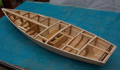
"bare hull" defintion of:
A model boat's outer shell, EXCLUDING, ribs, interior bulkheads, exclusive of masts, rigging, deck and equipment. Example. A fiberglass hull as pulled from a mold.
--
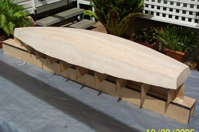
A wooden hull:
one constructed of wood (including plywood).
--
--
HULL defintion of:
The outer shell, including frames, ribs, interior bulkheads, exclusive of masts, rigging, deck and equipment.
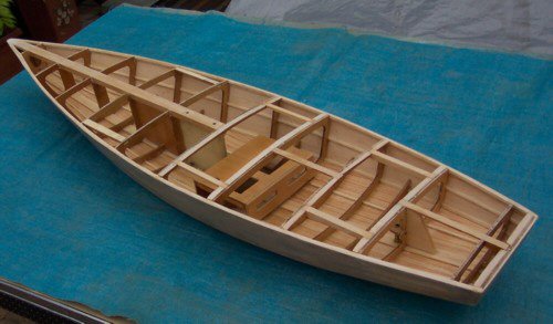
"bare hull" defintion of:
A model boat's outer shell, EXCLUDING, ribs, interior bulkheads, exclusive of masts, rigging, deck and equipment. Example. A fiberglass hull as pulled from a mold.
--
A wooden hull:
one constructed of wood (including plywood).

A glass hull:
one constructed of reinforced plastic (cloth impregnated with resin). Nominally referred to as a fiberglass hull.
one constructed of reinforced plastic (cloth impregnated with resin). Nominally referred to as a fiberglass hull.
--
A composite hull:
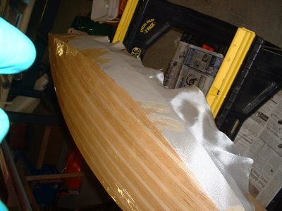
a hull constructed of wood and covered with reinforced plastic (cloth impregnated with resin).
 OR:
OR:
a hull constructed using a laminate (sandwich) consisting of reinforced plastic (cloth impregnated with resin) on two sides of a core . Core materials may be foam or wood.
a hull constructed of wood and covered with reinforced plastic (cloth impregnated with resin).
 OR:
OR:a hull constructed using a laminate (sandwich) consisting of reinforced plastic (cloth impregnated with resin) on two sides of a core . Core materials may be foam or wood.
Builders to do list,
Order Star 45 construction drawing from AMYA store
Buy or borrow books on boat building. Join the Star45 discussion forum.
Decide on type of planking and wood to be used to build the model.
Set aside a work space for building.
Review the bill of materials need to build the model and buy the materials.
Order deck and mast fittings.
Order mast (if you are buying the mast) and order sails (or sail material).
Choose the radio system, buy a sail control unit, Order keel bulb.
While the hull is under construction build:
Keel fin and ballast bulb
Rudder assembly
Make or assemble spars ( mast and booms)
Build cradel to hold boat under construction and when finished.
Test Radio System and sail control unit
After hull is planked:
Install keel trunk or provisions for mounting keel.
Install radio and sail control unit, Then remove while construction continues.
Contstruct deck and hatches
Install/mount deck fittings
Test access to radio and sail control inside the hull.
Provide a exit guide for radio antenna so it can be attached to mast or stays.
Install power switch for turning off batteries
Test mount keel
Paint hull, rudder and keel
Assemble hull, rudder and keel
Set up mast and boom.
Install radio controls.
Check running rigging.
Attach Sails
dry sail model
--
Sail
Display
Storage
Buy or borrow books on boat building. Join the Star45 discussion forum.
Decide on type of planking and wood to be used to build the model.
Set aside a work space for building.
Review the bill of materials need to build the model and buy the materials.
Order deck and mast fittings.
Order mast (if you are buying the mast) and order sails (or sail material).
Choose the radio system, buy a sail control unit, Order keel bulb.
While the hull is under construction build:
Keel fin and ballast bulb
Rudder assembly
Make or assemble spars ( mast and booms)
Build cradel to hold boat under construction and when finished.
Test Radio System and sail control unit
After hull is planked:
Install keel trunk or provisions for mounting keel.
Install radio and sail control unit, Then remove while construction continues.
Contstruct deck and hatches
Install/mount deck fittings
Test access to radio and sail control inside the hull.
Provide a exit guide for radio antenna so it can be attached to mast or stays.
Install power switch for turning off batteries
Test mount keel
Paint hull, rudder and keel
Assemble hull, rudder and keel
Set up mast and boom.
Install radio controls.
Check running rigging.
Attach Sails
dry sail model
--
Sail
Display
Storage
Sailing Model, AMYA Star45 Class | building board
"John Fisher" is building Star 45's. He has provided a series of photographs taken as he builds the model from scratch.
These are posted to the blog along with his notes to help builders assemble the Star 45.
In the following posts you will find comments, notes. and his photographs
Photo's showing the building board and the first couple of steps for putting the frames together.
Building board is 3" wide 3/4" MDF that is glued/screwed together.
The notched balsa template is glued to the building board using a straight edge. Use a staight edge to make sure it stays straight.
Sailing Model, AMYA Star45 Class | Rudder
AMYA Star 45 Class Rules, 2006, Rudder
6.1 Rudders may be constructed of wood, fiberglass, plastic, plastic laminates or metal. The exact shape is not specified, but they may not exceed 4 1/2 inches at the hull (fore and aft) 3 inches at the bottom, (fore and aft); and may not project more than 7 inches below the hull when measured at the post..
Subscribe to:
Posts (Atom)